VSI Crusher Rotor Build-up
The build-up in the rotor is a deliberately retained pocket of material that forms a surface over which rock slides and generally forms the shape of a wave with the crest toward the centre of the rotor.
Primary function
The build-up in the rotor needs to protect the internal walls of the rotor and most importantly protect the rotor tip from direct wear and impact.
Secondary function
The build-up in the rotor can influence the wear patterns of the wear parts in order of importance:
- Rotor tips
- Tip/cavity wear plates
- Upper and lower wear plates
- Distribution plate
- Feed eye ring
While large build-ups tend to assist in the protection of the above wear parts – particularly the rotor tips – they can greatly increase feed tube wear.
Crusher Rotor build-up Tuning
The success of the crusher is centered around its rotor. If the rock build-up within the rotor is ideal, then wear on the upper and lower wear plates will be even, the rotor tips fully utilized, and the lowest consumables cost per tonne of the product will be achieved.
Different material characteristics
Unfortunately, the build-up characteristics are never the same for any two materials, indeed the nature of the build-up will vary with rotor speeds, rotor sizes, feed rates, feed sizes, and feed moisture.
Tuning on site
Our factory delivery rotor will rarely work at optimum efficiency without some degree of tuning. Normally, some tuning will be required as each rotor is placed into service. Tuning relates to controlling the build-up of material within the rotor. This is done by altering the size, position, shape, or style of the trail plates.
Primary function
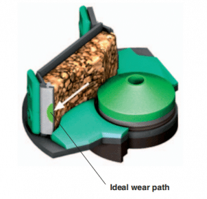
The main purpose of tuning is to ensure that the build-up within the rotor extends from the trail plate to the inserts in the rotor tip and that the wear is centralized across the rotor tips.
The insufficient build-up will result in tip exposure. This will lead to early failure of the rotor tips through the chipping of the inserts by direct contact with the larger stones in the feed. The insufficient build-up of material will expose the supporting metal of the rotor tips. This will also lead to premature failure of the inserts by direct abrasion from the stone flfl ow through the rotor. This can also result in the rotor tips wearing in front of the inserts which will eventually lead to their falling out of the carrier plate.
Basic principles
In tuning the rotor one should try to maximize the build-up within the rotor to achieve:
- A build-up of rock within the rotor to protect the wear parts and not restrict the feed path through the crusher.
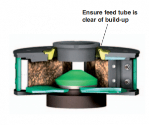
- A build-up that clears the side and bottom of the feed tube, preventing premature feed tube wear.
- An equal flow through each rotor port, equalizing the wear on the rotor tips.
The width and position of the trail plates control the amount and characteristics of the build-up in the rotor. The following is meant only as a guide, as rotor build-up is dependent on many factors: material type, moisture content, rotor speed, etc., and trial and error will have to be employed to determine the correct trail plate position for each application.
Generally –
- Wide trail plates make the material build-up deeper.
- Narrow trail plates make the material build-up shallower.
- Moving the trail plate away from the rotor tip makes the build-up deeper
- Moving the trail plate toward the rotor tip makes the build-up shallower
Areas to control
- Centralise wear over rotor tips
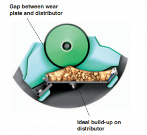
- Build-up on the distributor plate
- Clearance on the feed tube
- Clearance on the feed tube
Effect of rotor build-up adjustment
Centralising Wear over Rotor Tips
Will reduce wear on upper and lower wear plates. For deep rotors, it will reduce the wear on the top and bottom rotor tips.

Centralising Wear over Rotor Tips
Build-up on Distributor Plate
Stops fines swirling between distributor plate and wear plates which will damage the rotor body.

Build-up on Distributor Plate
Clearance on Feed Tube
Build-up rubbing on the feed tube generates heat and causes the feed tube to crack.

Clearance on Feed Tube
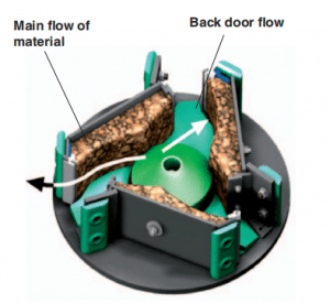
Back Dooring into Following Bed
Back dooring into the following rotor tip will cause tip to crack and fail prematurely.

Back Dooring into Following Bed

 Download Brochure
 Product List


