The track shoe casting is a critical component of electric shovels, accounting for 10% to 15% of the total equipment weight. As the walking part of mining equipment, it operates in harsh environments and experiences complex and variable stress conditions, quickly leading to wear, deformation, and even fractures of the track shoe. Large equipment track shoes are generally replaced in groups, with high replacement costs. Therefore, track shoes must have comprehensive performance characteristics such as high strength, wear resistance, impact toughness, and fatigue resistance. Currently, the materials for track shoe castings mainly include high manganese steel, low alloy steel, etc., with many models abroad opting for low alloy steel track shoes.
Low alloy steel retains wear resistance while offering better overall performance than high manganese steel. However, adding alloy elements in low alloy steel reduces the thermal conductivity of the alloy. It expands the solidification range, making it more prone to generate significant stress during solidification, leading to crack formation. Qiming Casting has researched the casting process of low alloy steel track shoes and encountered issues such as cracks and sand sticking during trial production. In response to these problems, this article optimizes the casting process of track shoes, eliminates casting defects, and produces qualified track shoe casting products.
Analysis of technical requirements of track shoes and difficulties in the casting process
Technical requirements
Chemical composition
The track shoes are cast from high-strength low-alloy steel and have good wear and impact resistance. The specific material is modified according to AS-1444-Grade4320. The chemical composition is shown in Table 1.
| Table 1. Requirement of chemical composition wb/% | ||||||||||
| C | Si | Mn | S | P | Mo | Ni | Cu | Al | V | |
| Min. | 0.21 | 0.3 | 0.8 | 0 | 0 | 0.4 | 1.4 | 0.03 | 0 | |
| Max. | 0.25 | 0.6 | 1.1 | 0.035 | 0.035 | 0.45 | 1.7 | 0.3 | 0.06 | 0.03 |
Quality requirements
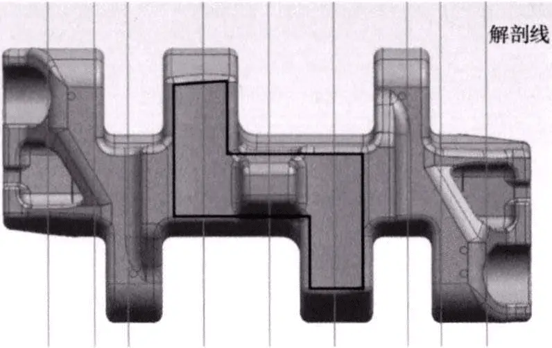
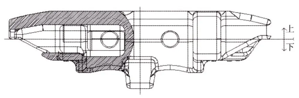
Based on the usage conditions of various structural parts of the track shoe, it is divided into critical and non-critical areas. The critical areas are the regions enclosed by the polyline in Figure 1 and the pin ear parts. During trial production, the castings must undergo overall visual, dimensional, magnetic particle, and ultrasonic inspections. After machining, the pin holes need to undergo penetrant inspection on the machined surface. After heat treatment, specimens must also be dissected as required, with the dissected locations shown in Figure 1. After dissection, penetrant, magnetic particle, ultrasonic, and radiographic inspections are carried out on the dissected surfaces. The surface finish of the casting should meet the requirements of ASTM A802 visual inspection standards, and the casting surface should not have sand sticking or oxide skin. Ultrasonic inspection is carried out according to AS2574-2000 – Castech ultrasonic inspection standards, with first-level requirements for critical areas and second-level requirements for non-critical areas. Radiographic inspection is carried out according to ASTM E94 – Standard Guide for Radiographic Examination, with defects in critical areas A, B, and C limited to less than 2nd grade, while defects in D, E, and F are not allowed. In non-critical areas, defects in A and B should be less than 2nd grade, C less than 3rd grade, and D, E, and F defects are not allowed. Due to strict quality requirements for castings, high demands are placed on the casting process.
Analysis of casting process difficulties
Product structure characteristics
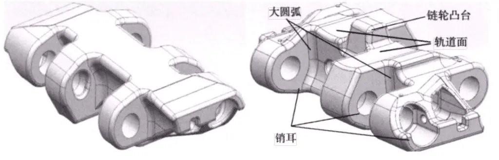
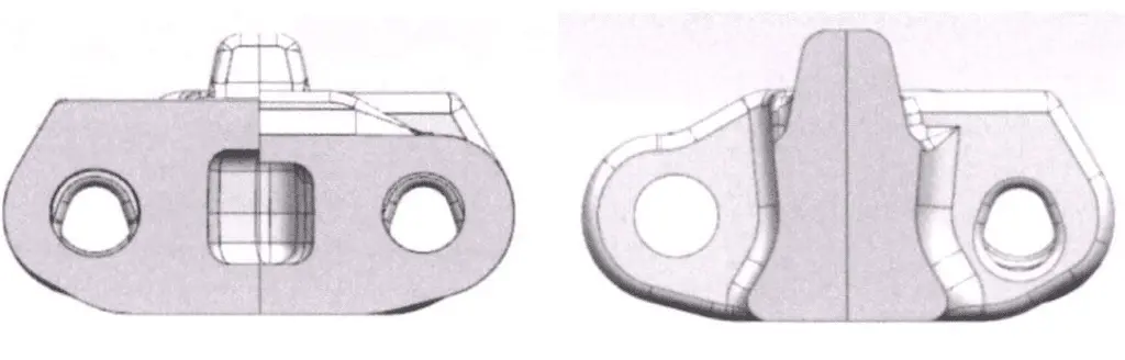
The track shoe is a critical component of the electric shovel, as shown in Figure 2. The individual weight of this product is 909 kg, with overall dimensions of 1,400 mm x 760 mm x 430 mm. The product has significant variations in wall thickness, with a maximum thickness of 190 mm and a minimum thickness of 40 mm, with the main thickness ranging from 70 mm to 120 mm. There are three pin holes on each side of the track shoe, which require machining. Using the product’s three-dimensional graphics allows for a clear observation of the internal structure of the casting. The track shoe can be divided into several mutually independent regions, including the central sprocket boss, six-pin ears, and thirteen large arcs connecting the pin ears to the body, as shown in Figure 2. The challenging cross-section is depicted in Figure 3.
Crack tendency analysis
The characteristics of alloys, sudden changes in wall thickness, and restricted shrinkage can all increase the tendency of castings to develop cracks. High-hardenability alloy castings are prone to martensite formation during welding, making cracks difficult to repair and even producing product scrap. Therefore, reducing the occurrence of cracks in track shoe castings is a crucial aspect of process design. According to the analysis of the casting structure, it is known that the arc portion connecting the pin ears to the body is the area where the casting is most likely to be hindered by the sand mold during solidification. This area undergoes significant wall thickness variations and is the most susceptible region to crack formation in the casting, thus requiring special attention in process design.
Casting Process Design of Track Shoe
Basic production conditions
The process involves using phenolic resin sand molding and core making and melting the alloy in a 2-ton medium-frequency furnace. Machine molding is adopted, with cores made manually. An alcoholic zirconium silicate powder coating is applied to the working surfaces of the sand molds and cores.
Parting surface selection
The track shoe is made of low alloy steel, and its liquid shrinkage and solidification shrinkage processes require a certain amount of molten steel to be consumed, thus needing to be replenished through risers to the casting. The track shoe’s tread surface, sprocket boss, and pin ears are critical areas and should be placed at the bottom of the mold first. At the same time, placing the large flat surface at the top of the mold facilitates the arrangement and cleaning of risers. To simplify the core structure and facilitate core removal, the parting line is designed on the plane where the center of the pin hole is located. The simplified casting process diagram is shown in Figure 4.
Sand core design
Based on the determined parting line, the sand core design for the track shoe casting is conducted, as shown in Figure 5. The sand cores for the six outer pin holes are cylindrical in structure, which is simple and easy to produce. The inner cavity sand core is overall L-shaped. A large core head is placed at the tail to provide positioning and fixing, while a cylindrical core head is placed at the head for auxiliary positioning and fixing, thereby preventing the displacement and floating of the sand cores.
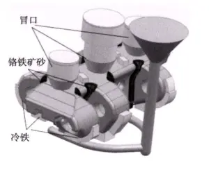
Riser and chilled iron layout
The main hot spots of the track shoe are the central sprocket boss and the connection points of the pin ears to the body, totaling 7 in number. By placing chills, the hot spots on the sprocket boss and its sides are combined into one hot spot. Chills are placed at the lower part and sides of the pin ears to allow two outer hot spots to share one riser. Therefore, only 3 risers are required for the casting, as shown in Figure 6.
Gating system design
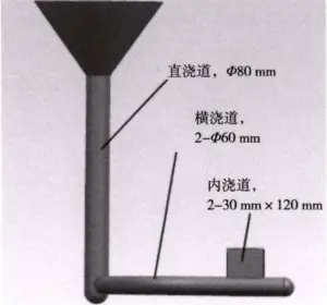
The casting gating system is the passage through which molten steel fills the casting mold cavity. A well-designed gating system can reduce the speed of molten steel entering the mold cavity, decrease turbulence, minimize steel oxidation, improve the smoothness of the pouring process, reduce the likelihood of porosity, and mitigate the impact of molten steel on the sand mold, thereby reducing the risk of casting defects. The gating system for the track shoe casting is shown in Figure 7, with the sectional area ratios of each component determined through calculations as follows: A Straight : A Transverse : A Inner = 1 : 1.12 : 1.43, constituting an open pouring system.
Chromite Sand Design
Compared to silica sand, chromite sand has higher refractoriness, which can reduce the tendency of casting sand sticking to the placement areas. Additionally, chromite sand can accelerate the solidification rate of the placement areas, enabling the casting surface in these areas to establish strength more quickly, thus reducing the tendency of cracking. From the structure of the track shoe, it is evident that the arc portion connecting the pin ears to the body is hindered by the sand mold during casting solidification, resulting in significant stress. Combined with the large wall thickness in this area, strength establishment is relatively slow, making it prone to cracking. Therefore, chromite sand should be placed in this area to reduce crack formation, as shown in Figure 6.
The regions where chills are placed on the casting surface and the surrounding areas experience significant temperature gradients during the solidification of the metal liquid, leading to shrinkage stress. Particularly, placing chills around thick sections of the casting generates significant stress, which can easily exceed the strength of the metal liquid film, causing crack defects. Placing chromite sand with good heat storage properties between the casting and chills can prevent crack formation. Therefore, in the process design of track shoe casting, chromite sand, 10~20 mm thick, is placed around the chills in thick sections of the casting.
Casting process feasibility prediction
Filling process simulation analysis
Figure 8 shows the filling process of the track shoe casting. At 1 second into pouring, the molten steel begins to fill the casting mold cavity, with a small amount of splashing occurring as the liquid enters, as shown in Figure 8a. Subsequently, the molten metal fills the casting mold cavity, starting from the bottom plane of the casting. After the bottom plane is filled, the molten steel gradually fills upward in layers, and the filling process proceeds smoothly. During the filling process, it can be observed from the temperature that the areas where chills are placed have the lowest temperature, followed by the edges of the casting.