The crawler shoe for a large mining excavator bears the upper weight and working load. The crawler shoe is an important part of the crawler device; its life is the core index of the equipment’s performance. In this paper, the dynamics simulation extracts the load spectrum of typical working conditions in the working cycle. The stress distribution of the structure under the action of unit force was determined by finite element analysis. Based on the finite element analysis, load spectrum, and S-N curve of the material, the fatigue life of the crawler shoe is obtained, which provides a theoretical basis for product design and field use.
Background
Mining shovel excavators are suitable for stripping and mining operations in large-scale open-pit coal mines, iron ore, and non-ferrous metal mines. The crawler device is an important part of the mining excavator. The crawler shoe is the core part of the crawler device. The life span of the crawler shoe not only affects the overall performance of the crawler device but is also of great significance to the inventory management of mining customers. Therefore, Qiming Casting conducted a fatigue life analysis on the track pads of large mining excavators.
Overview of Fatigue Life Analysis
This article uses ADAMS, NXNastran, NCode, and other software to calculate the fatigue life of mechanical mining excavators’ track shoes. The fatigue life analysis process is shown in Figure 1.
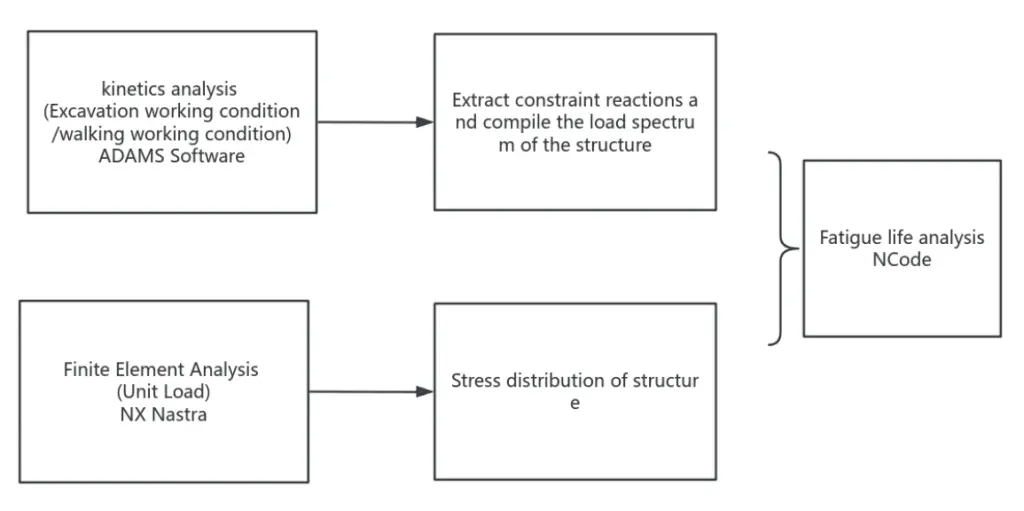
The excavator’s working process includes walking and excavation conditions. Compiling the structural load spectrum takes 3600s, of which 600s is the walking time and 3000s is the excavation time. The walking and digging time are each divided into five equal segments, and their load spectra are extracted from the dynamic analysis results.
Materials Analysis
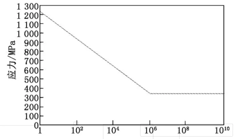
The track shoes in mechanical mining excavators are made of high-manganese steel, and their properties are shown in Table 1. The material’s S-N curve is shown in Figure 2.
| Table 1. Material properties of high manganese steel | |||
| Material | Modulus of elasticity (GPa) | Poisson’s ratio | Density(kg/m3) |
| Manganese Steel | 206 | 0.288 | 7829 |
Load spectrum analysis and calculation
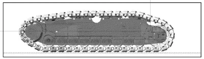
Figure 3 shows the simulation model of the excavator’s walking condition. The excavator’s mass is 1200t, the driving shaft speed is 17.2245s, and the simulation time is 150s. The load spectrum is compiled by dividing the walking into 5 sections, each lasting 120 seconds. Thus, the rotating pairs between the 5 track shoes are randomly selected for load extraction.
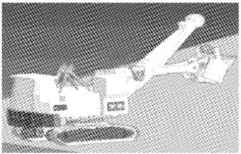
As shown in Figure 4, the simulation model of the excavation working condition is similar to the walking-working condition, in which the transmission of the excavation force is extracted from the reaction force at the rotating platform during the excavation operation simulation of the working device; the driving shaft speed is 0; the simulation time is 18s. In the preparation of the load spectrum, the excavation is divided into 5 sections; each section lasts 600 seconds, so 40 rotating pairs between the track shoes are randomly selected for load extraction, and the simulation results of 15 seconds are intercepted for each section.
In a pair of track shoes, the axial direction of the pin is the B axis, the gravity direction is the Y axis (Figure 5 shows the schematic direction of the track shoes on the upper side; the gravity direction is always downward), and the horizontal direction is the X axis.
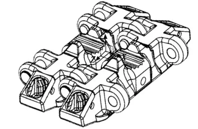
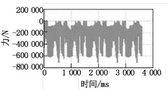
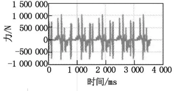
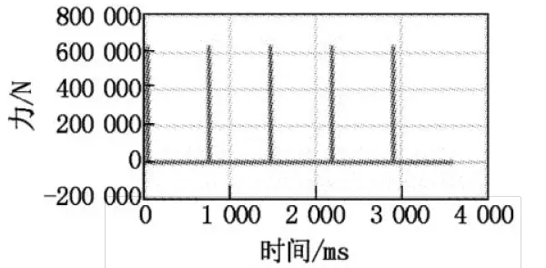
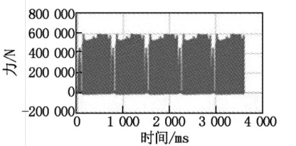
The values of the forces and moments in the Z direction are very small compared with those in the other two directions. Therefore, the force in the Z direction is not considered when compiling the load spectrum; only the forces in the X and Y directions are considered. In addition, the track shoes also bear the driving force of the active driving wheels and the overall pressure of the excavator. The compiled load spectrum is shown in Figures 6 to 9.
Finite element analysis
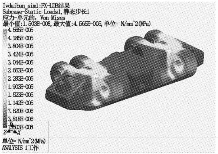
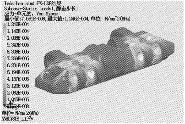
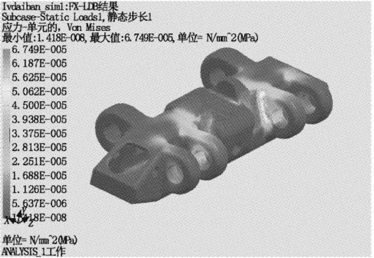
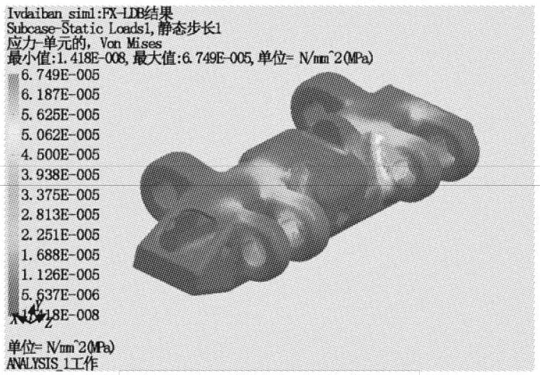
Finite element analysis is carried out to determine the stress distribution in the structure under unit force. In this case, simple constraints are applied on the binaural side, and unit load is applied on the monaural side. The stress distribution in the track plate under unit load is shown in Figs. 10 to 13.
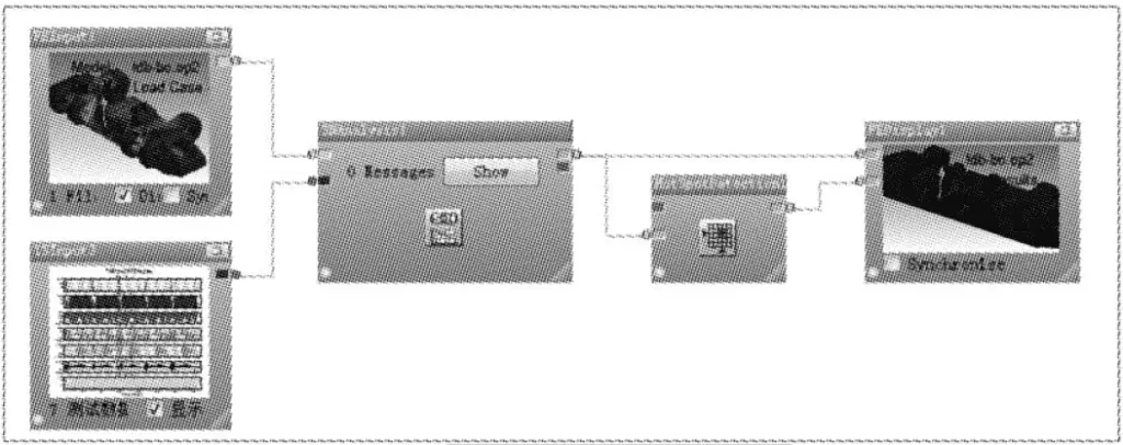
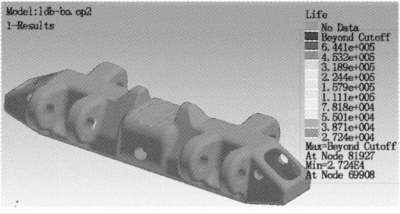
Fatigue life analysis
Fig. 14 shows the fatigue analysis process. The FEA and load spectrum results are introduced, and the material’s S-N curve is set for fatigue life analysis. The analysis results are shown in Fig. 15, which shows that the track plate’s design life is 27240h.