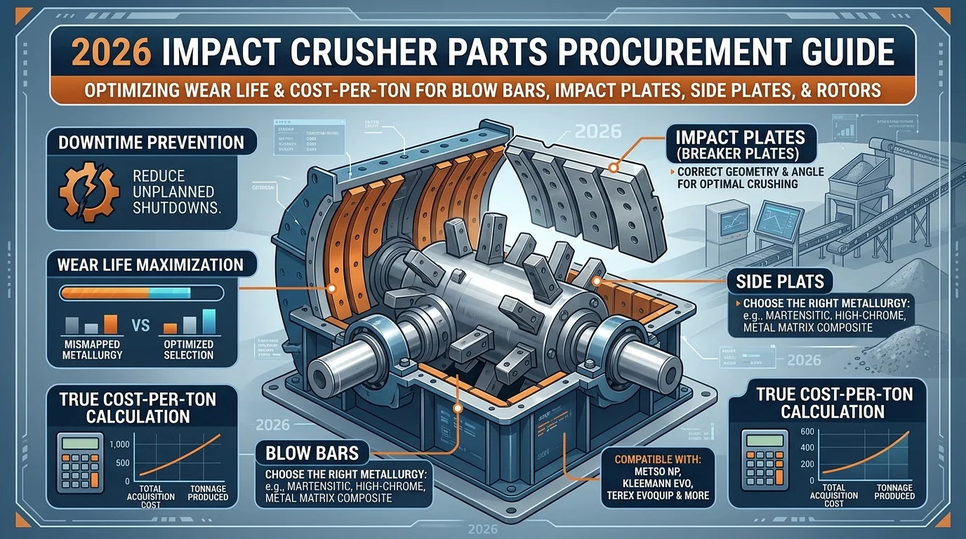
2026 Impact Crusher Parts Procurement Guide: Blow Bars, Impact Plates, Side Plates & Rotor
Every hour of unplanned downtime in a crushing operation costs thousands. The wrong wear part — mismatched metallurgy, incorrect geometry, or a substandard casting — doesn’t just wear out faster. It damages the rotor, shortens the life of adjacent components, and forces emergency replacements at the worst possible moment.
This guide covers everything procurement teams and maintenance engineers need to make confident sourcing decisions for impact crusher wear parts in 2026: blow bars, impact plates (breaker plates), side plates, and rotor components. Whether you operate Metso NP series, Kleemann EVO, Terex EvoQuip, or equivalent horizontal shaft impactors (HSI), the selection principles apply directly to your operation. By the end of this guide, you will have a clear framework to select the right metallurgy, avoid the most common procurement mistakes, and calculate the true cost-per-ton for each component.
Understanding the Four Core Impact Crusher Wear Parts
Impact crushing works at rotor speeds of 30–80 m/s — fundamentally different from compression crushing (0.5–1.5 m/s). At these velocities, wear part selection directly determines throughput, product shape, cost-per-ton, and equipment longevity.
Blow Bars
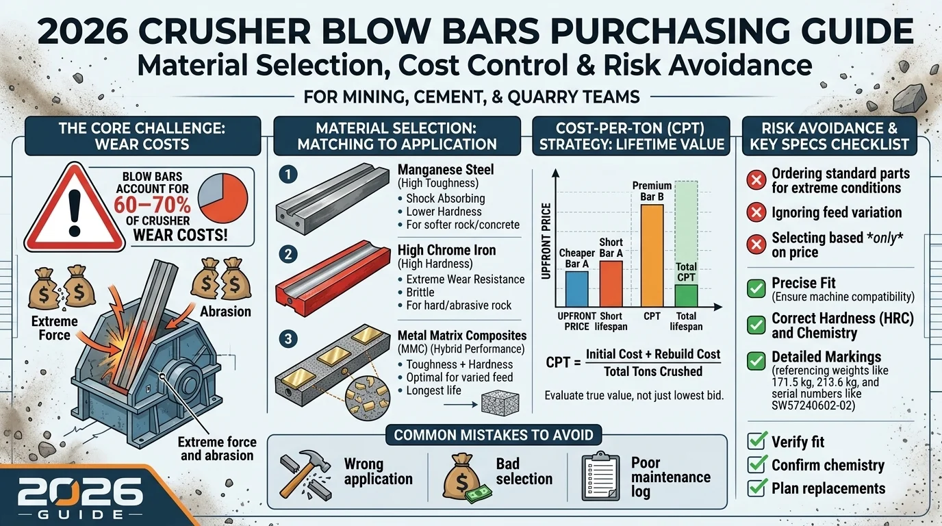
The primary crushing element. Inserted into the rotor, blow bars strike incoming feed material at high velocity. They account for typically 60–70% of total wear costs in an impact crusher (industry estimate; varies by application and material type). Material reduction occurs in three stages: initial impact with blow bars (60%), secondary impact with breaker plates (30%), and inter-particle collisions (~10%).
Impact Plates (Breaker Plates)
Primary and secondary breaker plates control final product size by defining the crushing gap. Protected by replaceable breaker plate liners, they redirect material back into the crushing chamber until it reaches the target size. The gap setting directly governs both product gradation and wear rate — tighter settings increase wear proportionally.
Side Plates (Side Liners / Frame Liners)
Mounted on the inner walls of the crusher body, side plates protect the frame from abrasive wear. Standard industry hardness is 400 Brinell (HB); premium aftermarket options are available at 450–520 HB, delivering measurable service life improvements. Two thickness options are common: 20 mm and 30 mm depending on abrasiveness of application.
Rotor
The rotor holds the blow bars and transfers centrifugal energy to the feed material. It is the most expensive component in an impact crusher — rotor damage from worn-through blow bars or improperly matched bars is the most costly procurement mistake in this category. Protecting the rotor through proper blow bar selection and timely replacement is the central logic of this guide.
Blow Bar Metallurgy: The Selection Matrix That Determines Your Cost-Per-Ton
No single decision in impact crusher parts procurement affects operating economics more than blow bar metallurgy. Five primary material categories exist, each representing a different balance between wear resistance and impact toughness — two properties that are inversely related in all metal alloys.
Manganese Steel (Austenitic)
Initial hardness: ~200 HV (20 HRC) | Work-hardened operational hardness: up to 500 HV (50 HRC) | Impact strength: ~250 J/cm²
Manganese steel work-hardens under repeated compressive and impact loading. The hardened layer penetrates approximately 10 mm into the surface, while the ductile core remains tough enough to absorb shock. This makes manganese uniquely suited to applications where:
- Feed material is very large (primary crushing, oversized feed)
- Unbreakable elements (tramp iron, rebar) may enter the crusher
- Material is low-to-medium abrasive (limestone, non-reinforced concrete)
Limitation: In low-impact applications, manganese does not work-harden effectively, resulting in poor wear resistance. It is not recommended for highly abrasive materials where chrome steel outperforms it significantly.
Martensitic Steel
Hardness: 44–57 HRC | Impact strength: 100–300 J/cm²
Martensitic steel sits between manganese and chrome in the toughness/wear resistance spectrum. It is the most versatile primary crushing blow bar — combining sufficient hardness to resist abrasive wear with enough toughness to handle large feed sizes and moderate iron contamination.
Best for:
- Primary blasted quarry rock
- Building rubble and concrete (with iron content)
- Large feed sizes (up to 900 mm on appropriate models)
- Recycling applications
Chrome Steel (High-Chrome Iron)
Hardness: 60–64 HRC | Impact strength: ~10 J/cm²
Chrome steel delivers the highest wear resistance of the standard alloy options. The hardness comes from chromium carbides in the matrix — extremely effective against abrasive wear but with critically low toughness. A single unbreakable element (steel bolt, rebar, excavator tooth) entering the crusher with chrome blow bars installed can cause catastrophic breakage.
Best for:
- Secondary and tertiary crushing stages
- Small, controlled feed sizes
- High-abrasion materials where feed is well-prepared
- Asphalt processing (no tramp iron)
Critical requirement: Feed must be free of unbreakable elements. No exceptions.
Medium chrome variants offer better impact resistance than high chrome, at some cost to wear resistance — a practical choice when feed size control is imperfect.
Metal Matrix Composites (MMC / Ceramic Insert)
The most advanced blow bar technology available in 2026. MMC bars combine a metallic matrix (martensitic or chrome steel) with ceramic particles infiltrated into the wear surface during casting. The result:
- 2–5× service lifecompared to equivalent mono-alloy blow bars
- Ceramic delivers extreme surface hardness; metallic matrix maintains structural toughness
- Ceramic insert is not visible when new — its presence is only confirmed after operating hours have accumulated
MMC variants and applications:
| Designation | Base Material | Target Application |
| Martensitic + Ceramic (e.g., Xwin® Martensitic) | Martensitic steel | Primary recycling, concrete, asphalt, quarry primary |
| Chrome + Ceramic (e.g., Xwin® White Iron) | Chrome iron | Secondary quarry/gravel, asphalt (no tramp iron) |
| High-performance MMC (enhanced matrix composites from specialist foundries) | Enhanced martensitic or chrome matrix | Very abrasive secondary conditions, gravel pits, steel slag |
Not recommended for: Slag recycling (too abrasive for ceramic), limestone in low-impact configurations (risk of metal stress from extended life).
Blow Bar Selection Summary
| Blow Bar Type | Wear Resistance | Impact Resistance | Feed Size | Tramp Iron Tolerance |
| Manganese Steel | Low–Medium | Very High | Very Large | Yes |
| Martensitic Steel | Medium | High | Large | Moderate |
| Chrome Steel (Medium) | High | Medium | Medium | No |
| Chrome Steel (High) | Very High | Low | Small | No |
| Martensitic + Ceramic | Very High | High | Large | Moderate–High |
| Chrome + Ceramic | Exceptional | Low–Medium | Small–Medium | No |
Note: MMC tramp iron tolerance depends on base material. Martensitic-based MMC inherits the moderate-to-good impact tolerance of the martensitic matrix. Chrome-based MMC retains the same zero tramp iron tolerance as standard chrome steel — carbide matrix fractures on unbreakable contact regardless of ceramic content.
Impact Plates & Breaker Plate Liners: Controlling Product Size and Wear Cost
How Gap Setting Affects Wear Rate
The crushing gap — the distance between the blow bar tip and the breaker plate — directly governs both product size and wear rate. Metso’s formula for first breaker plate setting provides a practical starting point:
S1 = (S2 + Feed Material Size) / 4 + 20 mm
For example: with a target product size (S2) of 40 mm and a maximum feed size of 300 mm, S1 = (40 + 300) / 4 + 20 = 105 mm. This becomes the starting point for upper gap adjustment, with fine-tuning based on observed product gradation.
Tighter settings increase fine particle production and accelerate wear on both blow bars and breaker plate liners. Operators chasing finer output without adjusting replacement schedules will see dramatically shortened component life.
Liner Rotation Strategy
Breaker plate wear is not uniform across the crushing chamber — wear is consistently higher at the bottom. Metso and similar OEMs design breaker plates with multiple same-sized liner sections precisely to allow positional rotation before full replacement. This extends total liner life significantly without requiring full plate changeout.
Key operational rule: individual worn liners can be replaced or repositioned independently. Full set replacement is unnecessary unless the majority of liners have reached wear limits simultaneously.
Breaker Plate Liner Materials
| Material | Hardness | Best Application |
| Manganese Steel | Work-hardens to ~400 HB | Primary crushing, high-impact applications |
| Chrome Iron | 550–700 HB | Secondary crushing, abrasive feed, controlled feed size |
Attachment systems differ by material — manganese liners use a bolt at the wear face; chrome iron liners use a hexagonal screw from the reverse side. Confirm fastener specification before ordering aftermarket liners.
Side Plates: The Overlooked Component That Protects Your Frame Investment
Side plates (side liners, frame liners, cheek plates) are frequently treated as secondary purchase decisions. This is a procurement error. Frame damage from worn-through side plates requires welding repair or structural replacement — costs that dwarf the price of timely side liner replacement.
Material Selection: 400 HB vs. 450–520 HB
The industry standard for side plate hardness is 400 Brinell (HB). Premium aftermarket grades at 450–520 HB deliver measurably longer service life — but the upgrade is only cost-justified under specific conditions:
| Hardness Grade | When to Select |
| 400 HB (standard) | Low-to-medium abrasive feed (limestone, non-reinforced concrete); controlled feed size; secondary/tertiary stages |
| 450–520 HB (premium) | Abrasiveness index above 600 g/t; basalt, granite, quartzite, or recycled aggregate with silica content; 4-bar rotor configuration at high rotor speed |
A practical threshold: if your French Abrasiveness Index exceeds 600 g/t, or if you are running a 4 × high bar configuration, the premium grade typically pays back in service life within the first replacement cycle.
Thickness options: 20 mm standard; 30 mm for high-wear applications or when upgrading from frequent replacement cycles.
When sourcing aftermarket side plates, require Brinell hardness certification with heat treatment documentation. Suppliers offering unverified “400 HB equivalent” without test reports represent a measurable procurement risk.
OEM Compatibility: What to Confirm Before Ordering
Side plate installation varies across crusher families:
- Bolt-on systems(common on Metso NP series, Kleemann EVO): plates are secured with spring washers and locking screws. Confirm hole pattern, plate dimensions (length × width × thickness), and fastener thread specification.
- Weld-on or retained systems(some Terex/EvoQuip configurations): require dimensional matching to the frame pocket geometry.
When requesting aftermarket side plates, provide: crusher model and serial number, plate position (drive side / non-drive side), and current plate thickness measurement. Dimensional drawings should be confirmed before volume ordering.
Side Plates and Blow Bar Configuration: The Operational Link
Side plate wear rate does not occur in isolation — it is directly influenced by rotor configuration and speed. A 4 × high bar setup at elevated rotor speed generates significantly higher lateral material velocity, increasing side plate wear by an estimated 30–50% compared to a standard 2-bar configuration at the same feed material (based on field observations from aggregate operations; actual variance depends on rotor speed and material abrasiveness). When planning blow bar upgrades or configuration changes, update your side plate replacement schedule accordingly.
Replacement Timing
Side plates wear at a significantly slower rate than blow bars — typically 3–5× longer service intervals in aggregate applications (varies significantly with feed abrasiveness and rotor configuration). Because wear is less visible during routine inspection, establish a scheduled measurement interval (every 500–750 operating hours as a starting reference; adjust based on your OEM manual recommendation and observed wear rate) rather than relying on visual checks alone. Track remaining thickness against the original specification; plan replacement before the wear face approaches the fastener zone.
Rotor Protection: The Most Expensive Component You Cannot Afford to Replace
The rotor is not a wear part — it is a capital component. Rotor replacement following blow bar damage is the most expensive maintenance event in impact crushing operations.
How Blow Bar Wear Damages the Rotor
When a blow bar is not turned or replaced at the specified wear limit, the following failure sequence occurs:
Blow bar wears through to the locking wedge contact area
Locking wedge becomes dislodged from its seat
Blow bar becomes unstable and can exit the rotor during operation
Rotor body sustains impact damage requiring hard-facing renewal or full replacement
All major manufacturers specify a minimum remaining dimension “D” before mandatory replacement or rotation. This dimension varies by model:
| Model Series | Minimum Wear Dimension (D) |
| Metso NP1110 | 55 mm |
| Metso NP1213 / NP1313 | 60 mm |
| Metso NP1315 / NP1415 | 70 mm |
| Metso NP1620 | 80 mm * |
| Kleemann EVO series | 15–20 mm (from reference face) * |
- NP1620 and Kleemann EVO values are based on supplier field data; always verify against your machine-specific manual before use.*
Always refer to the machine-specific manual for confirmed wear limits. Aftermarket suppliers should provide dimensional drawings confirming compatibility with rotor slot geometry.
Rotor Configuration: 2-Bar vs. 4-Bar
| Configuration | Feed Size Capability | Best Application |
| 2 × High bars | Large feed (0–600 mm+) | Primary crushing, universal applications, frequent material changes |
| 2 × High + 2 × Low bars | Medium-large feed (0–400+ mm) | Standard secondary, balanced throughput and reduction |
| 4 × High bars | Small feed (under 250–400 mm) | Maximum reduction, fine product target, high fines production |
Note: 4 × high bar configuration increases wear on blow bars, breaker plates, and side liners considerably. Rotor speed must be optimized for feed material when using this configuration.
Rotor-Related Components You Can Source Aftermarket
The rotor body itself is a capital component — not a standard procurement item. However, several rotor-related parts are high-frequency replacement items that aftermarket suppliers can and should stock:
- Locking wedges (clamping wedges):These secure blow bars in the rotor slot. They experience direct wear and deformation when blow bars are run past their wear limit. Always confirm wedge dimensions match your rotor slot geometry; weight and dimensional tolerances are critical. Order locking wedges alongside every blow bar set.
- Rotor bars / backing bars:The rotor backing surface behind the blow bar seat absorbs residual impact. On some machine families, these are replaceable without full rotor disassembly. Confirm applicability with your crusher model documentation.
- Rotor discs (where applicable):Certain modular rotor designs allow disc-level replacement rather than full rotor changeout. Check your OEM manual for component breakdown.
- Hard-facing renewal:When rotor body wear does occur — typically from a blow bar run past its limit — the repair path is hard-facing (weld deposit restoration) rather than part procurement. Budget this as a consequence cost in your maintenance planning: it typically costs several times the value of the blow bars that caused the damage (field estimates range from 3–8× depending on rotor size and damage extent).
When ordering any rotor-related aftermarket component, provide the crusher model, rotor diameter, and current part number (if available) to confirm dimensional compatibility before purchase.
Wear Pattern Diagnostics: 9 Problems and Their Root Causes
Worn blow bars tell a precise story about machine operation. Reading wear patterns before ordering replacements allows operators to address the root cause — not just replace parts.
| Wear Pattern | Root Cause | Corrective Action |
| Gentle radius across full face | Correct — all parameters optimized | No change required |
| Deep penetration notch | Rotor speed too low | Increase rotor speed; consider 4 × high bar configuration |
| Flat top wear, full surface | Rotor speed too high | Reduce rotor speed; switch to 2-high + 2-low configuration |
| Wear concentrated at center | Insufficient feed (trickle feeding) | Increase feed rate; upgrade feeder capacity |
| Wear at both ends | Excess fines in feed, or overfeed pushing material to sides | Reduce feeder speed; clean chamber daily |
| Wear on one side only | Machine not level, or uneven feed distribution | Level machine; correct feed chute alignment |
| Bar not turned before wear limit | Rotation schedule not established or not followed | Implement mandatory rotation schedule at 50% wear |
| Blow bar breakage | Wrong metallurgy for application, or tramp iron in feed | Review metallurgy selection; install tramp iron protection |
| Ceramic insert worn flush, no ceramic visible | Normal progression — ceramic exhausted | Replace with same spec or upgrade to higher-performance MMC |
The 5-Step Procurement Decision Framework
Step 1: Define Feed Material Parameters
- Rock type and abrasiveness (French Abrasiveness Test result or Abrasion Index)
- Maximum feed size
- Grain shape: cubic or plate-like
- Presence of unbreakable elements (tramp iron, rebar, excavator teeth)
Step 2: Select Blow Bar Metallurgy
Use the abrasiveness/feed size matrix above. When in doubt between two grades, choose the tougher option for primary stages and the harder option for secondary. Contact a metallurgical specialist for materials with abrasiveness above 1,200 g/t.
Step 3: Confirm OEM Compatibility
Verify:
- Rotor slot geometry — X-shape (Metso NP series), S-shape (Kleemann MR130), C-shape (Kleemann EVO generation, Terex/EvoQuip equivalent). Note: slot shape designations vary by supplier; always confirm compatibility using the OEM part number or dimensional drawing.
- Dimensional tolerances (blow bar length, height, weight)
- Weight matching: paired blow bars installed on opposite sides must not differ by more than 0.5 kg
Step 4: Calculate Total Cost of Ownership
Purchase price is one variable. The correct metric is cost-per-ton crushed:
Cost per ton = (Part price + installation labor) ÷ Tons crushed before replacement
A martensitic + ceramic blow bar at 2.5× the price of a standard martensitic bar that delivers 3× the service life reduces cost-per-ton by 17% — while reducing the number of change-outs and associated downtime.
Step 5: Establish Inventory and Replacement Protocol
- Stock minimum 1 full set of blow bars on-site at all times
- Document wear measurements at regular intervals (every 250–500 hours)
- Replace all blow bars simultaneously in most applications — mixed wear states create imbalance and accelerate rotor wear
- Exception: “slotted configuration” (2 new + 2 worn, diametrically opposed) can reduce fines output in specific secondary applications
Frequently Asked Questions
What’s the difference between martensitic and high chrome blow bars? Martensitic steel offers balanced hardness (44–57 HRC) and toughness (100–300 J/cm²), making it suitable for primary applications with larger feed and some iron contamination. High chrome delivers superior wear resistance (60–64 HRC) but very low toughness (~10 J/cm²) — it cannot tolerate tramp iron or oversized feed without risk of breakage.
Can ceramic blow bars be used in primary crushing? Martensitic + ceramic MMC bars are suitable for primary applications including quarry rock, concrete, and asphalt. Chrome + ceramic bars are not recommended for primary crushing due to their low impact toughness.
How do I know when to rotate vs. replace a blow bar? Blow bars are symmetrical and reversible — rotate at approximately 50% wear to use the second face. Replace when the remaining height reaches the manufacturer-specified wear limit “D.” Never operate beyond this limit; the risk of rotor damage makes the cost of delayed replacement far exceed the cost of the bar itself.
Are aftermarket impact plates compatible with OEM crushers? Yes, provided dimensional tolerances are confirmed and fastener systems match (bolt-in for manganese, screw-in for chrome iron). Request dimensional drawings and material certification (hardness test report) from your supplier before committing to a volume order.
What causes premature breaker plate liner wear? The most common causes: setting the gap too tight for the feed material, insufficient pre-screening (allowing excess fines into the chamber), and feeding wet or sticky material that accumulates in the crushing cavity. Address the operational root cause before ordering replacement liners.
Should I buy OEM or aftermarket parts? Quality aftermarket suppliers manufacturing to OEM dimensional specifications and equivalent or superior metallurgical standards can deliver comparable performance at 30–50% lower acquisition cost — when sourced from qualified suppliers with verified metallurgy. Verify: material certification, dimensional drawings, hardness testing documentation, and weight matching capability. The risk lies in unverified suppliers — always request hardness test reports and dimensional drawings before placing a volume order.
Partner With a Specialist Supplier
Impact crusher wear parts procurement is not a commodity decision. The interaction between metallurgy, feed material, machine configuration, and rotor speed means that the optimal blow bar for one operation can be the wrong choice for another running the identical crusher model. Getting it right requires the same technical depth this guide has outlined — applied specifically to your application.
A qualified supplier does not just deliver parts. They provide:
- Material certification— hardness test reports, chemical composition records, heat treatment documentation
- Dimensional drawings— confirming OEM slot geometry compatibility before volume commitment
- Weight matching— paired blow bars verified to within 0.5 kg tolerance to prevent rotor imbalance
- Metallurgical recommendation— based on your feed material type, abrasiveness index, feed size, and target product specification
- Lifecycle cost analysis— cost-per-ton comparison across metallurgy grades, so you are buying on value, not unit price
The procurement process is straightforward. Share your crusher model, feed material type, current blow bar specification, and average service life before replacement. We respond within 24 hours with a technical recommendation, lead time, and quotation.
[Request a Technical Quote] | [Download Blow Bar Selection Guide PDF] | [Contact Our Metallurgical Team]