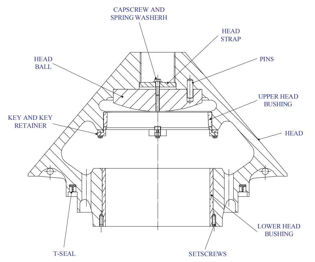
Lower Head Bushing
What is cone crusher lower head bushing?
A cone crusher lower head bushing is a component that is located at the bottom of the main shaft assembly, which is attached to the eccentric drive rotating assembly. The purpose of the lower head bushing is to support the weight of the main shaft assembly and provide a rotational interface between the main shaft and the eccentric assembly.
The lower head bushing is typically made of bronze or other high-strength alloys and is designed to withstand high loads and temperatures. It is usually located between the main shaft and the eccentric assembly and can be replaced if it becomes worn or damaged.
The lower head bushing plays a critical role in the operation of the cone crusher, as it helps to maintain proper alignment and reduce friction between the moving parts. It also helps to absorb the shock and vibration that is generated during the crushing process, which helps to extend the lifespan of the machine.
Lower Head Bushing Removal
The lower head bushing which has an interference fit with the head is held in place by setscrews. If the lower head bushing is to be removed for replacement, turn the head upside down and proceed as follows :
- Use a heavy-duty, industrial-grade circular saw equipped with a suitable metal cutting blade (head bushing is leaded bronze) to cut through the bushing wall in at least two locations. Adjust the saw blade so that it will clear the inner diameter of the bushing when resting on the bushing inner surface. Set the saw in the approximate location where the cut is to be made and position the saw so that the back of the saw base is flush with the end of the bushing.
- Measure the distance from the bottom of the saw base, at the point where the blade extends, to the outside diameter of the bushing. Subtract a slight amount from this distance to allow for irregularities and to be sure the blade will not be cutting into the head.
- Adjust the depth of saw blade to equal the distance determined in Step 2.
- Make a sample cut up to the full radius of the saw blade and check to be sure the blade has been adjusted to the correct depth. Re-adjust if necessary.
- Cut the bushing surface the entire length of the bushing.
- Repeat this procedure making the second cut at a point opposite the first cut. The bushing will collapse after the second cut is made.
- Remove setscrews and discard.
Lower head bushing installation
Install a replacement head bushing as follows :
- Clean the head bore and head bushing outside diameter using a wire brush.
- Pack the bore of the replacement bushing with dry ice to shrink the bushing. Approximately 90 kg (200 Ibs.) of dry ice is necessary to adequately pack the inside of the bushing if some sort of filler is used in the center of the bushing. As an example, a 100 mm x 100 mm (4″ x 4″) wooden timber leaves the sufficient area around it to allow for an adequate amount of dry ice to shrink the bushing. Wrap the outside of the bushing with several layers of fiberglass insulation to prevent the external build-up of frost which would hinder the installation of the bushing in the head. Wrapping also helps to achieve a more thorough cooling. Cooling time should be approximately 2 hours.
DO NOT USE THIS METHOD OF INSTALLATION TO OVERCOME A HEAD BORE THAT HAS CLOSED IN.
- Measure the outside diameter of the bushing and the bore of the head to determine when the bushing has cooled sufficiently.
- Install two ring bolts (from the toolbox) into the tapped holes in the bottom side of the bushing.
- Lift the bushing into position and center it at the top of the bore. Quickly lower the bushing into the head.
- Install the head bushing FLUSH with the bottom of the head.
- After the bushing has been installed in the head, drill and tap the head and bushing for holding setscrews.
- Install setscrews in the tapped holes with Loctite 277, after cleaning the holes and setscrews with an oil-free solvent such as alcohol or acetone. Make sure the head of the setscrew is FLUSH with the head or slightly below the surface of the head.
- Using a prick punch, «lock» the setscrews in the HEAD.
- Install the head following the instructions under INSTALLING HEAD ASSEMBLY earlier in this section. When reassembling the feed plate, be sure to caulk the area around the head of the capscrew and lock washer. This is an important seal that keeps dirt and water from infiltrating the feed plate capscrew and locking bolt threads.
AFTER THE NEW LOWER HEAD BUSHING IS INSTALLED, FOLLOW THE BREAK-IN PROCEDURE FOUND.
If you have any inquiries or problems with cone crusher parts, contact us freely!

 Download Brochure
 Product List


