Contact us
Please leave your specific needs and contact information, and the staff will contact you as soon as possible!
A cone crusher is a type of equipment used in mining and aggregate industries to crush a variety of materials, such as hard and medium-hard rocks, ores, and minerals. It is commonly used in the secondary, tertiary, and quaternary crushing stages. The crushing process is achieved by compressing the material between a mantle (concave surface) and a bowl-shaped bearing (concave). To make this possible, a cone crusher consists of several parts, each serving a specific function.
Those cone crusher parts include:
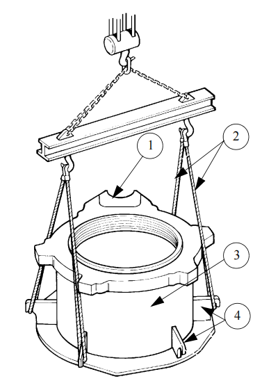
The bowl is screwed inside the adjusting ring, adjustments are made by rotating the bowl anticlockwise or clockwise, according to the desired setting.
Bowl adjustment determines the gap between the bowl liner and mantle.
The adjustment cap is fixed on top of the bowl and rubs against the joint of the protective apron that is fixed to the adjusting ring. This is done to protect the bowl and the locking ring. A set of locking cylinders are present at the top of the adjusting ring and around it. These cylinders push the locking ring and raise the bowl to the crushing position. The bowl rotates with the adjustment cap with the help of a hydraulic motor that is mounted on the adjusting ring.
The hopper is placed on two pins on the upper edge of the bowl. The inside of the hopper feeds the crusher cavity directly. The shape of the bottom of the hopper is designed in such a way that the materials build up there, forming a dead-bed that protects the hopper against the flow of feed material.
Several wedges and screws are present under the hopper and on the bowl, which hold the liner firmly on the bowl.
The crusher cavity is formed by the head, mantle, bowl, and bowl liner. The mantle is firmly held against the head with the help of a locking nut. The feeder cone rotates with the head and distributes materials in the crusher cavity.
The head has a bore that receives the head ball. The head ball is mounted tightly into the head. Two bores receive a bushing (upper and lower) that is also tightly mounted. The head ball rests on the concave part of the spherical bearing at the top of the main shaft. The lower head bushing is mounted with the play on the eccentric, and the head’s rotation is driven by being in contact with the ring and the eccentric.
When the machine is running idle, the upper head bushing comes into contact with the sleeve to maintain contact between the head ball and the sleeve. Holes in the main shaft guide the oil towards the upper and lower head bushings and into the spherical bearing.
A U-shaped seal machined over the imbalance matches the T-shaped seal mounted in a groove under the head to prevent oil leaks and protect the crown, pinion, and bushing surfaces from dust. A skirt acting as an oil deflector prevents leaks through the labyrinth seal.
The head assembly is supported by a sleeve that has a spherical bearing. This sleeve helps in transmitting the crushing force to the frame and is mounted on the shaft. It is fixed with screws.
The head ball is bolted under the head and is protected by the spherical bearing that is pinned to the top of the sleeve. The upper surface of the bearing is made up of circular oil grooves. The bearing is lubricated by pressurized oil flowing through the passages between the main shaft and the sleeve.
The eccentric part of the machine is positioned slightly off-center and at an angle to the vertical axis of rotation. This transmits the movement to the head. Inside the eccentric, there is a bronze ring, and at the bottom, a toothed crown is bolted to the eccentric.
The crown is driven by the countershaft pinion. The whole eccentric assembly rotates around the main shaft. The assembly rests on thrust bearings, with the upper thrust washer made of bronze and fixed to the bottom of the eccentric. The lower thrust washer is made of steel and fixed to the frame. These washers help to prevent wear in the assembly due to friction.
Adjusting wedges are used to maintain the play between and at the bottom of the teeth between the crown and the pinion. The imbalance is asymmetrical, so the greatest weight is positioned directly opposite the centrifugal force generated by the swaying of the head.
This imbalance creates an oil and dust seal between the rotating head and the fixed main frame. A system of baffles with “U” and “T” joints is used to maintain the seal.
The crusher’s countershaft motor receives power through either a V-belt transmission or a coupling sleeve, with a pinion at one end of the countershaft transmitting its rotation to the eccentric using a toothed crown.
The countershaft is supported by two bronze bushings, which are fixed in place by pins in the countershaft housing. These bushings have a flange that receives the axial load from the pinion and the oil deflector. The oil deflector is tightly inserted on the control side of the countershaft to spin the oil from the bushings’ lubrication and deposit it onto the cover.
The countershaft housing returns the oil to the tank, and it is firmly attached with large screws. An O-ring seal or a lip seal creates the oil seal between the frame and the countershaft housing, and a shield protects the countershaft housing from wear caused by falling crushed materials.
The frame, whether bolted to its foundations or mounted on a metal chassis with vibration dampers, provides an unyielding backbone for various components. The inside of the frame is safeguarded against wear by a liner that is welded to it, and arm liners that require periodic replacement.
The adjusting ring, which has a female thread for controlling the bowl, sits on a conical seating that is machined in the upper part of the frame. To prevent the bowl from turning during crushing, cylinders placed between the locking ring and the adjusting ring are used to press the locking ring against the inner face of the bowl threads. An apron fixed to the adjusting ring shields the locking cylinders and the bowl’s threads from dust.
Hydraulic cylinders pinned to the frame and traversing the adjusting ring keep the ring firmly pressed against the conical part of the frame. Under abnormal operating conditions or when tramp iron is detected in the crusher, the cylinder’s rods may pull and lift the bowl and the adjusting ring, causing strain. This movement forces the oil in the cylinders into the accumulators, where the nitrogen pressure increases.
Once the excess load has been released, the compressed nitrogen returns the oil to the cylinders, and the cylinder rods retract, causing the adjusting ring to return to its resting position on the frame. When the adjusting ring lifts off the frame, it is guided by vertical pins fixed to the frame.
Finally, the eccentric is supported by a thrust washer that is bolted to the frame’s drum, and play between and at the bottom of the teeth of the crown, and pinion is adjusted by wedges inserted under the washer.
Qiming Casting produces wear parts for cone crushers that are highly wear-resistant, easy to install, and have a longer lifespan. They achieve this by working closely with cone crusher users to understand their needs.
In addition to standard manganese liners (Mn14, Mn18, Mn22), Qiming Machinery also provides wear parts made from a variety of materials to meet the diverse needs of their customers.
Learn more about Qiming Casting cone crusher liner solutions→
Qiming Casting is the leading provider of high-quality aftermarket spare parts based on original drawings. We have successfully supplied replacement adjustment rings, eccentric bushing, head balls, countershafts, sleeves, and other spare parts for cone crushers and other major components that are no longer produced by the original equipment manufacturer.
Furthermore, we offer unbeatable OEM/ODM services for cone crusher parts that can be customized to meet your personalized requirements, including brand, label, painting colors, and packing box.
With our cutting-edge technology and experienced R&D team, we are confident in our ability to exceed your expectations. Don’t settle for less, choose Qiming Casting for all your spare parts needs.
Some common problems and solutions for cone crusher parts during machine operation
Effective Solutions:
Possible causes for the crusher using excessive oil include worn or damaged T and/or U seals, a faulty pressure relief valve, cold oil, overly viscous oil, poor ventilation, and blockages in the oil return caused by mud or rubble.
To address these issues, the following solutions can be implemented: replace worn or damaged seals, replace the relief valve if it is incorrectly set or remains closed, use an immersion heater to heat the oil to 27°C, use the appropriate type of oil, clean the breathers on the countershaft housing or cover, inspect and clean the oil return as needed, and ensure that the oil return gradient is at least 25 mm for every 300 mm or that the diameter of the oil return tube is adequate. Replace the oil return tube with a suitable one if necessary.
A blocked crusher can be caused by several factors, including loose V-type drive belts, electric problems with the motor, clogging under the crusher, slow countershaft speed, low oil pressure, feed opening issues, and wear on the bowl liner and mantle in the parallel zone, which can give them a “duckbill” shape and cause them to wear out quickly.
To resolve these issues, take decisive action. Tighten the V-type belts to ensure they are taut. If off-load and absorbed power are similar, have an electrician test the motor. Check the passage of materials under the crusher and fit a rotation checker on the discharge conveyor. Check countershaft speed, ensure correct oil pressure, and inspect the bowl liner and mantle profile. Cut the “duckbill” and replace the worn liner and mantle with suitable profiles. Don’t hesitate to take these steps to keep your crusher running smoothly.
Causes of Countershaft Failure:
1. Belts are tightly fitted.
2. Insufficient lubrication or oil in countershaft bushings.
3. Misaligned lubrication grooves in the bushing.
4. No play at the end of the countershaft.
5. Countershaft is bent due to excessive vibrations.
6. Clogged oil grooves in the outer countershaft bushing.
7. Broken crown or pinion teeth.
8. Incorrect play between teeth or at the bottom of the teeth between the crown and the pinion.
Effective Solutions:
1. Check belt tension and bull wheel alignment immediately.
2. Inspect the connection between the main oil pipe and the oil inlet in the countershaft box and remove any valve or device that may restrict the countershaft oil supply pipe.
3. Ensure that the belt drive doesn’t pull the countershaft against the lubrication groove.
4. Adjust axial play to a suitable measurement.
5. Replace the countershaft if necessary.
6. Clean oil grooves as soon as possible.
7. Replace the crown or pinion that has broken teeth.
8. Adjust the play between and at the bottom of the teeth without delay.
A blocked bowl can be caused by a variety of factors, such as accumulation of dust or rust in the threading, excessive heat, insufficient lubrication, damage to the adjustment cap cover, or dust prevention collar. Lack of weather protection and prolonged use of the crusher beyond the recommended settings can also contribute to the issue. Damaged or broken threads are other possible causes that can’t be ignored.
To tackle a blocked bowl, several solutions can be attempted. These include applying penetrating oil to the threads, relieving pressure in the holding and locking cylinders, feeding small pieces of wood or soft steel through the crusher, or heating the adjusting ring. When necessary, it may be required to heat the adjusting ring while simultaneously cooling down the bowl.
The oil leak at the end of the countershaft housing, bullwheel side can be caused by several factors, including insufficient oil return, a crusher that is not level, defective lip seals, and an unpressurized crusher.
To solve the problem, it is imperative to take action. Clean the breather of the countershaft housing, clean the oil inlet hole in the countershaft housing, replace the lip seals, and level the crusher to prevent further issues.
Wear and damage to the head span and bowl of a crusher can occur due to several reasons, such as running the crusher with a loose, damaged, or worn bowl liner and mantle or broken mantle and bowl liner. Additionally, during the run-in period of new bowl liner and mantle, intermittent feed can also contribute to the problem.
To address these issues, it’s imperative to ensure that the bowl liner and mantle are mounted correctly, and the locking nut is tightened adequately. Any excessive wear on these components can accelerate wear on the bowl and head spans, so it’s crucial to maintain them in good condition. If the bowl liner or mantle is broken, prompt replacement is necessary.
For crushers without a freewheeling clutch, starting the feed can loosen torque when the feed slows down head rotation. So, to avoid this problem, it’s best to avoid intermittent feed when new bowl liner and mantle are being mounted.
Several factors can lead to wear on the crown and pinion teeth, such as dirty oil, excessive or insufficient tooth wear, overworking of the crusher, and too much play at the end of the countershaft. To address these problems, the following solutions should be implemented immediately:
– Replace the oil and thoroughly clean the tank.
– Adjust the eccentric assembly with spacer rings if there are defective eccentric thrust washers.
– Remove the spacer rings to lower the eccentric assembly.
– Reduce the feed amount if there is ring bounce.
– Adjust play to the appropriate sizes without delay.
The following text discusses the problem of the adjusting ring being tilted and provides possible reasons for it. One reason could be the damage caused to the contact surfaces between the frame and adjusting ring as a result of ring bounce. Another reason could be too frequent overload or unsuitable bowl liner and mantle profiles, causing the adjusting ring to bounce.
To resolve this issue, here are some corresponding solutions: First, ensure that the feed is distributed correctly in the crusher cavity. If not, turn the ring 180° and check the pressure in the holding cylinders. If the pressure is too low, increase it. If there are too many fine products in the feed, refer to the paragraph “bowl liner and mantle selection” and increase the feed in the crusher. Additionally, increase the gap between the bowl liner and mantle. If materials are clogged, water the feed.
The locking bolts on the feeder cone are broken due to several reasons, which need to be addressed assertively. These reasons may include having too much feed in the crushing chamber, feed containing large pieces of product, worn contact surfaces between the feeder cone and the locking nut, loose feeder cone bolts, and drops that are too high.
To address these issues, it is imperative to implement several corresponding solutions, including reducing the amount of feed, reducing the size of input products or increasing the admission opening by changing the bowl liner and mantle, hard-surfacing and re-machining the locking nut, replacing the feeder cone, tightening the bolts to their thread torque, and reducing the drop between the feed box/belt and the feeder cone. These measures need to be taken immediately to prevent further damage and ensure efficient functioning of the feeder cone.
Some reasons may lead to the sleeve being unlocked:
– Too fine a feed can cause irregular wear on the bowl liner and mantle, which affects grip. This can be corrected by replacing the bowl liner and mantle or adjusting the bowl for a larger opening.
– Operating at too low or high a speed can also affect production. So, it’s important to check the countershaft speed.
– The presence of too much debris in the feed, such as wood, roots, etc., can also reduce production. This can be remedied by removing the debris.
– Large materials at the feed can prevent correct feed and reduce production. Reducing the dimensions of the materials at the feed can help.
– Sticky material in the feed can block the bowl liner and mantle inlet, which can affect production. Removing sticky products can help.
– Incorrect feed distribution can also cause problems, so it’s important to ensure correct feed distribution.
– The bottom of the mantle having a “duckbill” shape and the bowl liner and mantle in the parallel zone area wearing too quickly are also possible reasons for reduced production. These issues can be addressed by replacing the bowl liner and mantle or using another type of profile.
Common Causes of Oil Leak:
An oil leak problem can arise due to the following reasons:
– Worn out or damaged T and/or U seals.
– Damaged or worn O-ring or lip seals in the countershaft housing.
Effective Solutions:
To address the oil leak issue, you should implement the following solutions without delay:
– Replace the seals immediately.
– Replace the joints and thoroughly clean the pinion side interlocking and lag with silicone.
Possible causes of water mixing with oil include water accumulation through the imbalance cover and a blocked breather on the oil tank.
You can drill holes and weld return tubes or replace the breather to resolve the issue.
Analysis Problem:
The bowl mantle or liner detachment can occur due to several reasons, including:
1. Incorrect thread torque of the nut’s locking bolt, and the play between the screw’s head and the locking nut is not correct.
2. The locking nut is positioned incorrectly on the spacer ring.
3. The locking nut knocks against the top of the head.
4. Liner/mantle or head spans are damaged.
5. Insufficient play for the seal between the mantle and the head.
6. Cylindricality defect.
7. The mantle is not secured to the head.
8. The mantle is not centered on the head.
9. The mantle rotates too long without feed.
10. The mantle is too thin.
11. The old sealant resin was not entirely removed before installing the new mantle.
12. The tightening lugs of the bowl liner touch the outer diameter of the liner.
13. The bowl liner is too thin.
14. Too much tramp iron passes through the crusher.
15. The span on the bowl liner or bowl is damaged.
16. The old sealant resin was not entirely removed before installing the new bowl liner.
Corresponding Solutions:
1. Apply the correct thread torque.
2. Change the locking nut.
3. Keep a play between 6mm to 10mm between the bottom of the locking nut and the top of the head.
4. Remake the spans.
5. Maintain a play between 6mm to 10mm.
6. The gap between the bottom of the mantle and the gauge should not exceed 0.1mm.
7. Dismantle the mantle and reinstall it correctly.
8. The maximum time without feed should not exceed 30 minutes.
9. Wear should not exceed 2/3 of the mantle.
10. Remove all the old sealant resin.
11. Wedge the lug or tighten the screw.
12. Wear should not exceed 2/3 of the bowl liner.
13. Too much tramp iron will loosen the bowl liner.
14. Remake the spans to the original dimensions.
15. Remove all the old sealant resin.
Ensure that the above solutions are implemented correctly to prevent any future detachment issues.
Excessive vibration in a crusher is a serious issue that needs to be addressed immediately. The following reasons may cause this problem: imbalance or worn-out liner, incorrect adjustment at the bottom of the teeth, bent countershaft, difficulty of the bullwheel’s rotation, unsuitable foundation, loose or worn-out bowl liner, high countershaft speed, or missing imbalance liner.
Fortunately, there are corresponding solutions to tackle these issues. It is imperative to take immediate action and implement these solutions. These include remaking and replacing the imbalance liner, reassembling the eccentric and wedging it, replacing the countershaft, removing accumulated dust on the spokes of the bullwheel, checking the seating and foundations, dismantling the bowl liner and replacing it, using the correct speed, and replacing the liner and seeking professional assistance. Don’t let excessive vibration in your crusher go unchecked; take action now to prevent further damage and safety hazards.
Analysis Problem and Solutions
Dust entering the lubrication system is an unacceptable problem that requires immediate attention. The problem can be caused by:
– No breather on the crusher.
– Malfunctioning breathers on the crusher or the oil tank.
– Crusher bullwheel sending dust towards the breather.
– Dust penetrating the crusher while dismantling parts.
– Steep oil return between the crusher and the tank.
– Lack of seal between the oil tank and its cover.
– Damaged or disconnected hose between the fan and the countershaft housing.
– Damaged or disconnected breather hose or couplings.
In order to resolve the issue, we suggest that you take the following assertive actions:
– Install a breather on the top of the countershaft housing.
– Clean the breathers on the countershaft and the oil tank. To verify effectiveness, hold a sheet of paper on the breather pipe while the crusher is running; it should be sucked slightly inwards.
– Position the breather further away from the bullwheel.
– Cover the sleeve and the eccentric with a plastic sheet.
– Add another breather on the oil return pipe to prevent dust from entering the sleeve.
– Seal the oil tank and its cover using a sealant or silicone to avoid future dust penetration.
– Inspect the hose and the couplings between the fan and the countershaft housing thoroughly.
– Check the breather hose and the couplings for any damage or disconnection.
We strongly recommend that you implement these solutions as soon as possible to avoid any further damage to the lubrication system.
There are certain reasons that could result in the issue of noise on the drive gear and pinion.
Some of these reasons include incorrect play between the teeth and at the bottom of the teeth, or the crusher running with a new crown and an old pinion, or vice versa.
The corresponding solutions to these issues are to adjust the play and there is no need to change anything.
Analysis Problem and Corresponding Solutions:
The Bowl bounce problem can be caused by several reasons, including wear on the adjusting ring and bowl threads, lack of pressure in the locking cylinders, crusher adjustments being too narrow, and the bowl liner and mantle being too thick. Additionally, a wide gap adjustment can also lead to bouncing.
To resolve these issues, the following assertive solutions are recommended:
– Re-machine the surface of the threads at a 45° angle to obtain a uniform slope (if the threads are not irreparably damaged).
– Restore the normal pressure in the locking cylinders.
– Increase the gap until the bowl no longer jumps.
– Mount a thinner bowl liner and mantle if there are not enough threads engaged.
– Reduce the gap if there are not enough threads engaged.
– Ensure that the hose between the cabinet and the locking cylinders is “taut” when the hydraulic unit is running.
These solutions will effectively address the Bowl bounce problem.
There could be several reasons for the problem of Bounce on the adjusting ring, such as overload or incorrect profile of the bowl liner and mantle, operation with too little cylinder pressure, etc. To address this issue, one should consider solutions like reducing the excessive quantity of fines in the feed, avoiding too much feed, opening too narrow, or avoiding sticky materials.
In addition, one should also check for cylinder seal defects, ensure that the unit repressurizes the cylinders automatically (by checking the pressure switch), and fix any leaks in the cylinder circuit valve, cylinder pressure relief valve, or hose and coupling.