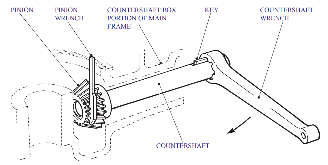
Disassembly of countershaft assembly and pinion replacement
Whenever the eccentric assembly is out for inspection or replacement of parts, it is advisable to inspect the pinion for wear or broken teeth. Pitting or galling on the face of the teeth are good indications of excessive wear. This can be due to improper tooth contact resulting from an incorrect quantity of shims being placed under the lower thrust bearing, by overloading the Crusher or using excessively dirty oil. A worn pinion is more susceptible to tooth breakage. Also, running on a worn pinion could lead to structural damage in other parts due to vibration. Excessively worn pinions should be replaced. To get the maximum benefit from new parts, it is recommended that the gear and pinion be replaced at the same time. If a new pinion is run with worn gear, the root clearance must be checked as instructed under CHECKING BACKLASH CLEARANCE.
Disassemble the countershaft assembly for replacement of bushings, pinion, or other worn parts, as follows:
- Remove the bowl, head, socket, and eccentric assemblies.
- Remove the crusher sheave as described under CRUSHER SHEAVE REMOVAL.
- Remove the oil flinger cover and packing ring from the flinger.
- Heat the oil flinger to approximately 27°C (50°F) above ambient temperature.
- Place a pry bar between the oil flinger and the countershaft box portion of the main frame and exert moderate pressure. Once the flinger starts to move, grasp each side of the flinger and pull the finger straight off the shaft.
- Break loose the capscrews holding the lockplate to the pinion lust enough to take the pressure off the internal threads of the pinion. Since the capscrews were installed with Loctite, the capscrews must be heated with a torch to approximately 205′ C (400° F) before the capscrews can be unscrewed.
- Position the special «saw-toothed» pinion wrench between the pinion teeth and the left edge of the pinion well on the main frame.
- Place the large countershaft wrench over the end of the countershaft taking care that the key in the wrench engages the keyway in the countershaft. Strike the wrench with a heavy-duty sledgehammer to rotate the countershaft in a COUNTERCLOCKWISE direction.
- Install a ring bolt (lifting eyebolt) in the tapped hole between the teeth on the pinion and connect to a suitable lifting device. Then unscrew the countershaft completely from the pinion and lift the pinion out of the cone crusher.
- Remove the lockplate from the pinion by unscrewing the previously loosened capscrews.
If you have any questions or cone crusher parts inquiry, please contact us freely.

 Download Brochure
 Product List


