VSI Crusher Shaft Line Assembly

VSI Crusher Shaft Line Assembly
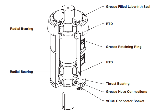
The shaft line assembly is a grease-filled, sealed bearing assembly that can be removed in one piece (shaft, bearings, seals, and housing) for overhaul and inspection. When the new shaft line assembly has run between 100 and 150 hours, begin a series of routine checks on the run-down time of the rotor (time from power being cut to rotor stops turning). A significant decrease in the run-down time over a period will indicate that the bearings (crusher or motor) are deteriorating. Once the time falls below two minutes the bearings should be checked at the next routine service time.
Operators should become familiar with the sound of the bearings running. If this noise changes, especially if it begins rumbling, this will also indicate that the bearings are deteriorating.
If, when standing on top of the rotor during servicing, the shaft can be rocked from side to side with excessive float, then the radial bearings are worn.
If the no-load current begins to increase slowly over a period of time, this is an indication that the crusher bearings are worn.
Upper seals should be replaced and the labyrinth repacked with grease at yearly intervals.
Seal
Many premature shaft line assembly failures can be attributed to the failure of the upper seals within the assembly. It is recommended these upper seals be inspected initially after 500 hours of operation and then at intervals of 2000 hours of operation and replaced if found to be worn or broken. This inspection/replacement can be done with the shaft line assembly installed in the base of the crusher and with the rotor removed.
Every care should be taken during the inspection to ensure seals and shaft line assembly labyrinth remain free of dust.
The lower seals cannot be inspected or replaced while the assembly is installed in the base but are very unlikely to cause a premature failure of the assembly. These seals are always replaced during any repair/reconditioning process.

VSI Crusher Seals
To inspect/replace upper seals:
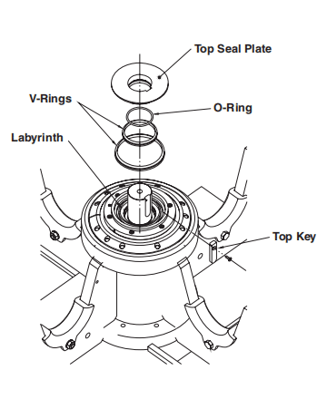
- Remove the top key and slide the top seal plate off the shaft.
- Remove the O-ring from within the top seal plate. This is a static seal and may have a flat surface from contact against the shaft. If the seal is not broken or obviously damaged in any other way, it can be reused.
- Inspect the labyrinth between the bearing and the outermost seal. This should always be fully packed with clean grease. If the grease is not clean, the v-ring seals are not effective and must be replaced. If the labyrinth is not completely packed with grease, there could be a problem with the grease supply to the shaft line assembly (check hoses, etc) or with the lubrication schedule.
- Remove the one or two v-ring seals (depending on the model) from the upper bearing retaining ring. These should not be worn, cracked, or broken.
- Refit/replace seals as necessary, pack the labyrinth with grease, and refit the top seal plate and key.
- Refit the rotor and start the crusher. Apply twice the normal amount of grease to each grease point and continue with normal operation.
Removal from base
- Remove the hopper and crusher roof in one lift.
- Remove the rotor.
- Loosen off the belt tension and remove the drive belts.
- Remove the crusher pulley. In larger models, use a VSI pulley lifter or a threaded rod (in the threaded hole in the shaft) and support to assist in lowering the pulley.
- Remove grease hoses and grease chutes.
- Remove VOCS plug.
- Release the bottom taper ring by removing the taper ring bolts.
- Screw half of these back into the top of the tapped extractor holes to force the outer taper ring off.
- Remove the bottom inner taper ring.
- Remove the top taper ring bolts.
- Use extractor grub screws to remove the top taper ring.
- Insert the lifting eye bolt into the top of the shaft.
- Lift out shaft line assembly.
Refitting in base
- Remove all traces of grease, protectant, dust, etc, from machined surfaces using thinners or similar solvents.
- Ensure all mating surfaces are free from rust, dents, scratches, etc.
- Apply a thin layer of heavy machine oil to the mating surfaces of the shaft assembly, housing, and taper rings.
- Lower the shaft line assembly into the top of the housing and check to see that the three plastic grommets are still in place. This will ensure the grommets are not lodged in the housing.
- Check the orientation of the assembly. The grease discharge slot must align with the grease discharge chute.
- Locate shaft line assembly centrally with top taper ring.
- Fit bottom taper rings (inner and outer) and lightly screw in bottom taper ring bolts.
- Fit grub screws in until just below flush with the top of taper rings and secure in place with silicone.
- Refer to shaft line assembly bolt torque settings.
- Starting on the top taper ring, torque down bolts top and bottom in a “star” sequence in two stages. Repeat for the bottom taper ring.
- Refit grease hoses, making sure they are not twisted or blocked. Identification of grease points on shaft line assembly. Ensure that grease hoses are not able to fall onto drive belts during operation. Note: Some models have a bar to rest the grease hoses on.
- Reconnect VOCS plug.
- Refifi t pulley and drive belts.
- Refifi t rotor.
Qiming Casting is a China VSI crusher wear parts manufacturer, we supply kinds of wear parts for all popular brands of VSI crushers. If you need any brands of shaft line assembly, please contact us!

 Download Brochure
 Product List

